Table des matières
Integration in Domoticz of a Local Air Conditioner Delongi Penguino EX Series
This tutorial is divided into three sections
- Part I objective is to understand how works the infrared remote control of Delonghi Penguino air conditioner.
- Part II objective is to develop hardware and software to build a Software Controlled Infrared Remote Control (SCIRC)
- Part III objective is to integrate the SCIRC into Domoticz
Prerequisites
- The tutorial assumes that you are familiar with Linux (Raspbian), the MQTT protocol, the Raspberry Pi.
- You must be familiar with SSH connection (for connection between your PC and the Raspberry Pi.
- You must also have a basic knowledge of electronics.
- And for sure, you must be familiar with Domoticz
What do you need ?
- a computer under Windows or Linux or MacOs with a SSH client such as Putty on Windows (required only during the development phase)
- 1 x Raspberry Pi (Rpi) Zero W and its 5v/1A power supply
- You must install the most recent version of Raspbian and on it the
mosquitto,gitand the librarywiringpi. - You must enable the SSH server on your Rpi.
- 1 x integrated circuit NE555
- 1 x integrated circuit 74HC00
- 1 x NPN transistor 2N2222 (or equivalent)
- 1 x infrared led
- 1 x infrared receiver and demodulator VMA317 or equivalent (required only during the development phase)
- Various resistors and capacitors
- 1 x breadboard for prototyping and various breadboard wires (Male/Male, Male/Female, Female/Female)
- a Domoticz server
- a Wifi local network
- an oscilloscope or another Raspberry Pi (type 3) with PiScope installed on it.
Part I : Understanding the Penguino remote control
About LIRC
As soon as you work with infrared transmissions, the first thing that comes on the Internet is the LIRC software package, which has been adapted for RPi. I finally gave up using it. LIRC works very well in reception, but I've never been able to get it to work in transmission. I finally developed my own solution that is very simple and resource-efficient. If you are a LIRC fan, there is no need to go any further in this tutorial.
Understanding how the IR remote control works
Penguino EX Series air conditioner are provided with an Infrared Remote Control (IRRC).
It is therefore necessary to understand how it works, meaning which kind of transmission protocol and code it uses.
Figure 2

The NEC transmission protocol
After many tests using my numeric oscilloscope I have found that the IRRC is based on the Nec IR Transmission Protocol. Details on this protocol are provided here.
In brief the remote control transmit a sequence of bit (0 or 1). Transmission is carried by a 38 kHz carrier frequency. Any press on the remote control causes the transmission of a 32-bit frame preceded by a header and ended by a stop bit.
The first 16 bits are address bits that can be used to distinguish one device from another. They are therefore invariant for all the keys of the same air conditioner. The last 16 bits, namely the data bits, are used to code the different keys of the remote control. For a given key, (e.g. ONOFF) the data bits are probably the same from one air conditioner to another.
Decoding the frame of the Delonghi Penguino air conditionner
So the codes I'm about to give you are those of my air conditioner. The first 16 bits will certainly be different on yours. On the other hand, the last 16 bits will certainly be identical. This is why you will not escape an analysis phase of your frames using an oscilloscope or Piscope.
Figure 3 below shows the frame emitted by the remonte control when the ON/OFF key is pressed
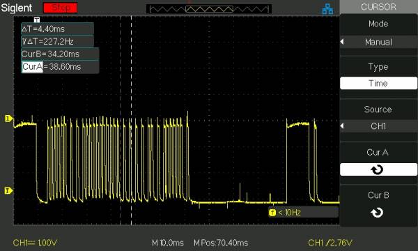
On this figure, the right hand pulses are repeat codes automatically sent when you keep the pressure on a key.
Figure 4 shows more details of the frame (the header is hidden here)
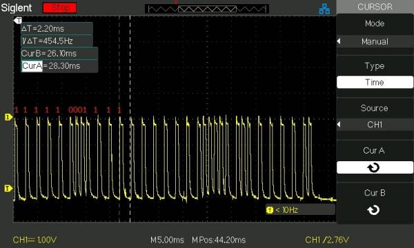
Looking at this frame, it is easy to decode the value of the ONOFF key (see red indication on the figure)
Each burst (or MARK) followed by a short SPACE is a 0 and when the burst is followed by a long SPACE it is a 1.
Then on this figure we can easily decode the following sequence of bits : 1111 1000 1111 1111 1100 0001 0011 1110 (F8FFC13E in hexadecimal). By the way you can see that the data bits (key code) are transmitted twice, first as a normal byte (1100 0001) followed by an inverted byte (0011 1110) which complies with the NEC protocol. This is not true for the adress bits which is not fully compliant with the NEC transmission protocol.
Figure 5 shows the same frame using PiScope.
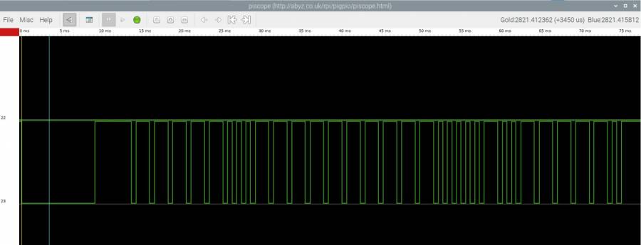
On the above figure, the signal is inverted compared to the signal provided by my oscilloscope.
Indeed PiScope shows the real signal delivered by the receiver and demodulator VMA317 (see more details below).
It is inverted compared to the NEC definition simply because the VMA317 module has an inverted output.
You can see that it is very easy to decode the signal using Piscope, so it is a very economical solution if you do not have an oscilloscope. More information on Piscope can be found here
I have done the above analysis for each key of the remote control and finally I have got the following results.
Table 1 - Keys coding of the Delonghi Penguino series EX remote control
| Key name | Code in hexadecimal |
|---|---|
| ONOFF | F8FFC13E |
| MODE | F8FF837C |
| FAN | F8FF03FC |
| PLUS | F8FF21DE |
| MINUS | F8FF01FE |
| TIMER | F8FF817E |
| OSC | F8FFA15E |
| HOME | F8FF41BE |
| SILENT | F8FF619E |
Do it yourself
As mentioned above, you will need to decode your own remote control because the 16 address bits of your remote control will be different of mine.
To do so, you will need the VMA317 module which is very easy to use. You just need a 5 volts power supply or more simply you can use the 5v available on pin 2 or 4 of the GPIO connector of the RPi.
The VMA317 Module
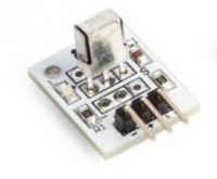
For more information on VMA317, look at the datasheet that you can find here.
In brief, this module has 3 pins :
- pin 1 is the ground that you can connect to pin 6 of the RPi and to the ground of your scope.
- pin 2 is the 5V power supply that you can connect to pin 2 or 4 of the Rpi
- pin 3 is the signal you will apply to the input of your oscilloscope or Piscope.
Once the VMA 317 is connected, let point the Penguino remote control (Figure 2) at the VMA317 module and press a key. On the VMA317 a red LED should light up for a short time and simultaneously the signal decoded by the module must be displayed on your oscilloscope or your Piscope. If no signal appears, it may be a trigger problem to fix on your oscilloscope. Finally, you should get something like shown on Figures 3, 4 or 5. It remains to decode manually the bits and to repeat the job for each key of the remote control. Carefully, note the values of the codes in hexadecimal, it will be needed later in the software part.
Part II : Hardware and Software
At this stage of progress, you know how the keys of your Penguino remote control are coded. Now you will build the Software Controlled Remote Control. It will be controlled by the Raspberry Pi Zero WH and will generates an exact replica of the Penguino remote control.
The hardware
The hardware is inspired from the schematics your can find here. I have done some improvement to get a better signal shape and to increase the transmission power of the emitting infrared LED. It must be implemented on your breadboard.
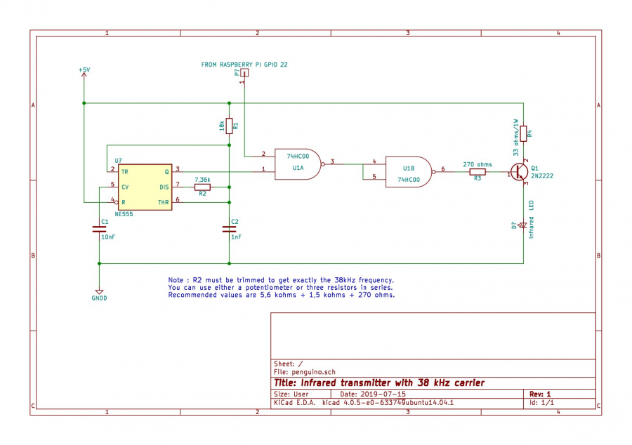
The heart of this schematics (Figure 6) it the timer NE555 which generates the 38 kHz carrier. If you use ordinary components (resistor and capacitors) and because of their inaccuracy (10 to 20% variation around the nominal resistance or capacitance value), there is little chance that you will get exactly the 38 kHz frequency.That's why I recommend replacing the 7.36 kohms resistance with a 10 kohms potentiometer that you adjust to get the right frequency (use your oscilloscope or Piscope for that). If you don't have a potentiometer on hand, you can do like me: use a combination of three resistor values connected in series. For example: 5.6 Kohms in series with 1.5 Kohms in series with 270 ohms. Then to obtain exactly 38 kHz you can replace the 270 ohms with one of the standard values immediately lower or higher among the following 120, 150, 180, 330, 390 etc., until you approach with sufficient accuracy the 38 kHz.
As shown on Figure 6, pin 3 of NE555 delivers the 38 kHz signal which is applied to pin 1 of a NAND gate (U1A). On pin 2 of this gate you will apply the signal that will be generated by the software of the RPi we will see later. This signal is an exact replica of the one delivered by the remote control. It will be provided on GPIO 22 (pin 15 of the GPIO connector of the Rpi). So you must connect the GPIO 22 (pin 15) of the Rpi to the pin 2 of the U1A on your breadboard (Figure 6). The output of the NAND gate (Pin 3 of the U1A) is connected to pin 4 and pin 5 of another NAND gate (U1B) which acts as an inverter. Then on output of U1B (pin 6) you will get the replica of the remote control modulated by the 38 kHz carrier. This signal is applied through a 270 ohms (R3) resistor to the base of a 2N2222 transistor which controls the current of the infrared LED mounted in its emitter. A 33 ohms/1W resistor (R4) is mounted on its collector to limit this current. Finally don't forget to connect pin 7 and pin 14 of the 74HC00 respectively to the ground and to the 5V and a 0.1uF filtering capacitor between +5V and GNDD (not represented on Figure 6). Figures 7-a, 7-b, 7-c show respectively the implementation on a prototyping board (7-a) and on a veroboard (7-b) that plugs into an RPi Zero WH (7-c).
Figure 7 (a,b,c)
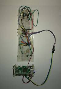
Prototype

Veroboard

Verboard + RPi
Note that the intensity required by the infrared LED is much higher than the current the Rpi can deliver on its +5v-GND pins.
To overcome this difficulty I added to the schematic a 2000 mF (micro Farad) capacitor between +5v and GND. It acts as a “current reservoir” and therefore provides for a short time the expected current. As the remote control is not very often used, the capacitor has time to recharge and is always ready to deliver the expected current. Note that this 2000 mF capacitor is not shown on the schematic (Figure 6). If you apply this solution, pay attention to the polarity of the capacitor, otherwise you will have to use an external power supply.
The software
At this step, I assume that you are familiar with ssh. Then, using Putty (or any other ssh client) you must connect your PC to the raspberry Pi which will execute the software.
The software is written in C. You can get it on Github (File ''irsend.c'')
The source program is sufficiently commented to understand it without too much difficulty if you have some knowledge of C programming language. And if you use to program in Python, it's finally quite similar.
Once you have downloaded the source program from Github and before compiling it, you must make some changes in the source code. Indeed, you just have to replace the key code values of my remote control by the key code values of your remote control. Edit the file irsend.c with you favourite text editor (nano is mine) and modify the following lines
 #define KEY_ONOFF	0xF8FFC13E
 #define KEY_MODE	0xF8FF837C
 #define KEY_FAN	0xF8FF03FC
 #define KEY_PLUS 	0xF8FF21DE
 #define KEY_MINUS 	0xF8FF01FE
 #define KEY_TIMER	0xF8FF817E
 #define KEY_OSC      0xF8FFA15E
 #define KEY_HOME	0xF8FF41BE
You just have to replace the hexa value of each key by the value you found during the oscilloscope (or Piscope) analysis. Then it is time to compile the source program and to link it to the wiringPi library.
pi@ecu3:~ $ gcc irsend.c -o irsend -lwiringPi
Now you can test it by typing the following command which will cause the infrared LED to emit the frame corresponding to the ONOFF key on the remote control.
pi@ecu3:~ $ ./irsend -k ONOFF
Tests ans toubleshooting
There are two ways to verify that it does what it was intended to do. The first consists in using the VMA317 module and visualizing the transmitted frame on the oscilloscope. It must be a replica of the one emitted by the remote control. The second way is to plug in your Penguino and see if it starts after this command is issued.
And if it doesn't start, it may be that the distance between the air conditioner and your transmitter is too long for its limited range, so you will have to bring it closer.
But I must insist on one cause of malfunction: timing. I have observed that it is imperative to respect the timing indicated in the standard defined by NEC. In particular, the total duration of the frame must be as close as possible to 67.5 ms (excluding the last stop bit). In irsend.c, it is the call to the nanosleep(…) function which allows the different timing to be defined, but it is imprecise. That's why an trimming coefficient has been added that you may have to calibrate.This calibration will be done by successive tests until the total frame duration of 67.5 ms is measured with the oscilloscope (or Piscope). By default this coefficient is 850 but you can modify it with the option -c <integer value> when you run irsend.

And if it still doesn't work, then you will have to go back to the first test method using VMA317.
Once it works for the ONOFF command you can test the other commands for example SILENT and check that it works correctly on Penguino. If one of the commands does not work while the others work, it is probably because you whave made a mistake in decoding. Once all command has been successfully tested you can move to the next step.
pi@ecu3:~ $ ./irsend -k SILENT
Part III : Integration into Domoticz
As the air conditioner is not necessarily in the same room as your Domoitcz server, it will be necessary to use a distributed architecture composed of the two following elements:
- the Domoticz server installed on an Rpi (or other) also called the publisher;
- the client, a RPi Zero WH coupled to the infra-red interface described above also called the subscriber. It should be positionned as close as possible to the air conditioner
Publisher and subscriber must be on the same local network connected by Wifi or Ethernet. They have their own IP addresses that we will name later in this tutorial IPP and IPS for the publisher and the subscriber respectively
The principle is as follows: on the server we will install a virtual device that will represent the remote control. Each press on a button of this virtual remote control will cause a message to be sent to the client, which will be interpreted by the client to generate the infrared emission of the corresponding command.
Messages will be in JSON format. The protocol used to transmit them will be MQTT.
Step 1 : MQTT implementation using Mosquitto
There are many tutorials explaining the MQTT protocol, its implementation with Mosquitto and how to install Mosquitto on Raspberry Pi on Debian.
We invite the reader to refer to them. An example in French is on this link.
MQTT relies on a Broker, one or more publishers and one or more subsribers. In our implementation, the Rpi supporting the Domoticz server will play the role of both Broker and Publisher while the Rpi Zero will play the role of Subscriber. Follow the tutorials to configure Mosquitto for this purpose and make a test to verify that a message sent by the publisher is received by the subscriber (this test is to be performed independently of Domoticz).
Step 2 : Domoticz server configuration
On the Domoticz server you have to create a virtual hardware as shown on figure 8
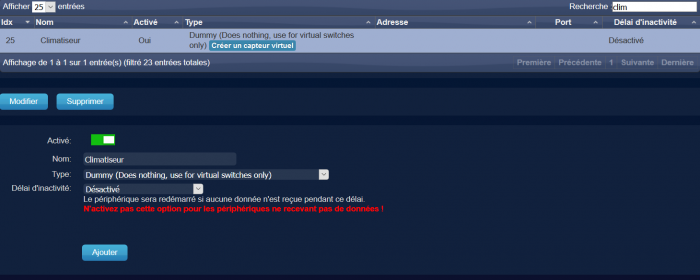
Figure 8
Then you create a “Selector switch” device that after creation you will find on the “Switches” Menu of Domoticz (Figure 9).

Figure 9
The switch will not look exactly as shown in figure 9 because it has to be configured. To do this click on the “Edit” button and configure the switch as shown in figure 10 below.
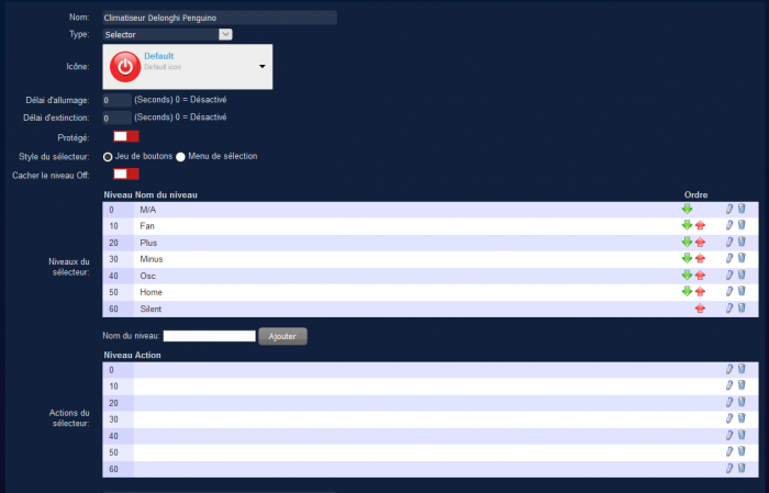
Figure 10
Now launch the following command on the client Rpi (the subscriber):
mosquitto_sub -h IPS -v -t "domoticz/out
where IPS (e.g. something like 192.168.1.XX) is the IP address of the Rpi supporting the Domoticz server.
Now let's go on your Domoticz server and press a button of your Air Conditionner device. You should receive on client side a Json message very similar to this one (below)
 domoticz/out {
    "Battery" : 255,
    "LevelActions" : "||||||",
    "LevelNames" : "M/A|Fan|Plus|Minus|Osc|Home|Silent",
    "LevelOffHidden" : "false",
    "RSSI" : 12,
    "SelectorStyle" : "0",
    "description" : "",
    "dtype" : "Light/Switch",
    "id" : "00014393",
    "idx" : 835,
    "name" : "Climatiseur Delonghi Penguino",
    "nvalue" : 0,
    "stype" : "Selector Switch",
    "svalue1" : "0",
    "switchType" : "Selector",
    "unit" : 1
 }
Two fields are important in this JSON message : idx and svalue1
Step 3 : Client (or subscriber) configuration
All the required source codes can be downloaded from Github
Note: In the following, we call MYIP the IP address of your Domoticz server and MYIDX the idx of the device which represents the Penguino on your Domoctz server. MYIP should be something like 192.168.1.XX or 192.168.0.XX or something very similar depending on your local network configuration. I suppose, of course, that you have assigned static IP addresses to your client and server Raspberry Pi (for this you have to configure the DHCP section of your router or internet box).
Step 3-a : filtering JSON message
As you can see, there is a lot of useless information in the JSON message. Also perhaps other JSON frames can be received from other devices.
Therefore, filtering is necessary for :
- process only the frame related to the air conditioner device: we will use the
idxfield for this purpose - extract the value from the
svalue1field
This filtering is done by the small program jsonextractor.c that you can also download on Github. Before using this filter you have to compile jsonextractor.c.
gcc jsonextractor.c -o jsonextractor
This filter reads its input data (the JSON frames) on its standard input (stdin) and delivers the filtered information on its standard output (stdout). Thus, it is easy to see the effect of this filter with the following command:
mosquitto_sub -h MYIP-v -t "domoticz/out" | ./jsonextractor -i MYIDX
By pressing some buttons on the virtual device you will see the following output of the filter
 0
 20
 40
corresponding respectively to action on button ON/OFF, PLUS and OSC in this example
Step 3-b : sending infrared code
It remains to send the infrared codes with the interface connected to your Rpi Zero WH. The irsend program will take care of it. In the first part of this tutorial we used it by indicating in the command line the code to send. By launching this same program in “domoticz” mode (option -d) irsend executes an endless loop and waits for the arrival of commands on its standard input. These commands are simply the codes delivered by the jsonextractor filter. Each time a code is received (0, 10, 20, 30 etc), irsend causes an IR code corresponding to the desired command to be transmitted. This is achieved with the following command:
mosquitto_sub -h MYIP -v -t "domoticz/out" | ./jsonextractor -i MYIDX | ./irsend -d
where the output of moquitto is piped to the input of jsonextractor of which the output is piped to irsend.
Now, place your Rpi Zero as close as possible to your air conditioner and do the tests.
Step 3-c : Concluding
You just have to fix this command a little bit before placing it in a script so that it will be automatically launched at the boot of your Rpi. To do this, you have to indicate complete paths for jsonextractor and irsend. Something like that:
mosquitto_sub -h MYIP -v -t "domoticz/out" | /home/pi/penguino/jsonextractor -i MYIDX| /home/pi/penguino/irsend -d
to adapt to your own configuration.
Tricks and tips
- You can use the same software to remote control a LG TV by specifying the
-loption when launchingirsend. See theirsend.csource code to know which remote commands are supported. Feel free to extend irsend.c to remote control other device. Add the relevant options for that. - Maybe your TV or Penguino will require a repeat code : use the
-r <integer value)option when launching irsend where<integer value>is the number of repeat code. See example below with 10 repeat code.
mosquitto_sub -h MYIP -v -t "domoticz/out" | /home/pi/penguino/jsonextractor -i MYIDX| /home/pi/penguino/irsend -d -r 10
- Maybe your TV or Penguino will require the command to be send by bursts : use the
-b <integer value>option when launching irsend where<integer value>is the number of bursts. See example below with 3 bursts.
mosquitto_sub -h MYIP -v -t "domoticz/out" | /home/pi/penguino/jsonextractor -i MYIDX| /home/pi/penguino/irsend -d -b 3
- Example of
rc.localfile
 #!/bin/sh -e
 #
 # rc.local
 #
 # This script is executed at the end of each multiuser runlevel.
 # Make sure that the script will "exit 0" on success or any other
 # value on error.
 #
 # In order to enable or disable this script just change the execution
 # bits.
 #
 # By default this script does nothing.
 # Print the IP address
 _IP=$(hostname -I) || true
 if [ "$_IP" ]; then
   printf "My IP address is %s\n" "$_IP"
 fi
 (/usr/bin/mosquitto_sub -h 192.168.1.39 -v -t "domoticz/out" | /home/pi/penguino-domoticz/jsonextractor -i 1029| /home/pi/penguino-domoticz/irsend -d -l -r 5 2>>/home/pi/penguino-domoticz/lgtv.log) &
 (/usr/bin/mosquitto_sub -h 192.168.1.39 -v -t "domoticz/out" | /home/pi/penguino-domoticz/jsonextractor | /home/pi/penguino-domoticz/irsend -d  -r 5 2>>/home/pi/penguino-domoticz/penguino.log)  &
 exit 0
Finally, note that if you are an expert in sed and/or jq you can avoid using the jsonextractor program and design your own filter using these commands. Personally I am not such expert to do that.

